Tensegrity
Instructors: Cory Zurell
Team: Individual
Materials: Wood Dowels, Clear String
Winter 2022

Principle of Tensegrity
Tensegrity structure, also known as a Tension Integrity structure, is a system of compression members within a network of tension members. The entire structure is in continuous tension, and within a traditional tensegrity structure, none of the compression members physically touch. An American Architect, Buckminster Fuller, crowned the term tensegrity as a “self-tensioning structure composed of rigid structures and cables, with forces of traction and compression, which form an integrated whole”.
The principles of the structure revolve around the idea of using compression and tensile forces arranged in a way that complements each other to create a strong, lightweight, and flexible structure that can carry loads easily. These types of tensile structures are commonly used for pavilion, art, roof, and bridge structures, and often use metal as the compressive materials and wires for the tensile members. Tensegrity structures use a very little amount of material and can continuously grow if the structure is constructed and balanced correctly based on its center of mass and stiffness.
Process of Assembly for Model
The traditional tensegrity model, standing at 16.5cm tall, is made up of two materials: 6” wooden dowels, and clear non-compressive wire. Each dowel has a two-millimetre-deep notch, on either side, where the clear wire will be housed. Each of the six dowels uses a 14” long wire, simply tied on each end of the wire, and wrapped around the dowel in the longitudinal direction. The tied knots on either end of the wire act as “wedges” in the notch to ensure the wire doesn’t slip once under extreme tensile forces. The 6 members are arranged in a “parallel” fashion (shown below) and create a tension point at the midpoint of another dowel. Mid-point placement of each dowel ensures equal tensile forces moving to both notches at either end.
To begin the organization of members, every singular dowel needs to run perpendicular to two other dowels on each side of the singular dowel. These two dowels that run perpendicular to the singular dowel attach at the midpoint of the tensile wire on either end of the singular dowel as mentioned before. The continuous process of adding two perpendicular dowels to a singular is done till every tensile member, the clear wire, is in a notch on the end of a dowel. Once every tensile member is set in a notch, the structure should be able to stand on its own tensile resistance. This is when the model can be adjusted so that every dowel is at a direct midpoint of a tensile wire to ensure a structural balance once loaded.
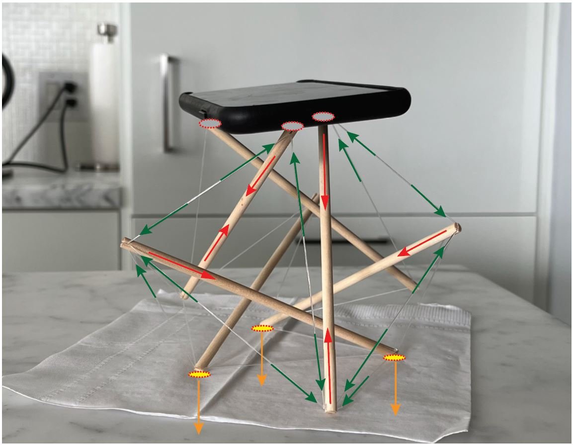
Load Path
The load path for the physical model is straightforward but looks complex. The phone sits on three contact points on the model while the weight of the phone travels through the first three dowels. These dowels are held up through the tensile wires, which hold themselves on the notches of the next three dowels. These three dowels carry the load to the surface the model sits on.